How to determine the number of connected PCBs
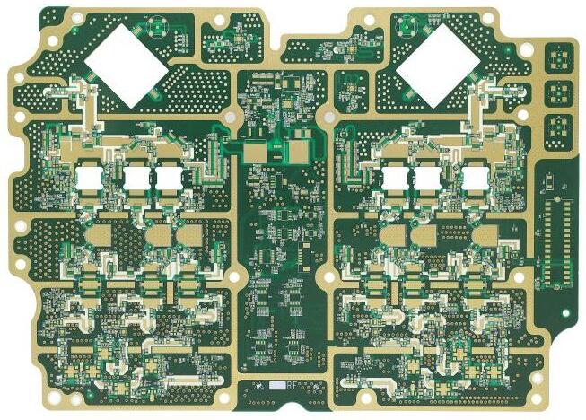
Generally speaking, after the design engineer has determined the appearance of the printed circuit board, he should immediately proceed with the work of plywood/splicing/panelization of the circuit board. The purpose of connecting plates is to increase the output of the production line. 2. Reduce the loss of sheets. The most common connecting board usually combines two or more identical circuit boards into a large circuit board, such as 2 in 1 (two in one), 3 in 1 (three in one), 4 in 1 (four in one), etc. There are also cases where different shapes of circuit boards can be combined into a large board, but this is rare because it is difficult for the "Planner" to match the exact number of different boards when arranging production.

More relevant reading: The advantages of using "Yin Yang Board" in PCBA also include making the same board into [Yin Yang Board]. [Yin Yang Board] mostly means the top and bottom configuration, which is usually applied to circuit boards with few parts, such as mobile phone boards, because it can make full use of SMT's long line printing function to increase efficiency, but the disadvantage is that the use is limited, and may cause uneven heating of parts, For example, some circuit boards will focus on the design of a certain side of the heavier parts, and then this side will be used as the second printing to prevent the heavier parts from falling off when reflow soldering is repeated. Of course, it is difficult to use the design of [Yin Yang Board] for such boards. Some boards may have heat absorbing parts (such as a large ATM card reading slot), which is not suitable for the [Yin Yang Board] design. Of course, there are also flexible [Yin Yang PCB Board] methods to overcome this problem, but I won't discuss them here. Basically, the following factors should be considered when designing the number of boards. In fact, no matter how the production or design is carried out, it is ultimately inseparable from the consideration of money. Therefore, all the factors should be converted into the amount to make the final measurement standard to select a suitable board splicing method. Considering the optimal utilization rate of circuit boards, general circuit board manufacturers will have their basic standard board sizes for rapid mass production and cost reduction, such as 16.16 "x16.16", 18.32 "x18.32", 20.32 "x20.32", etc. What we need to do is to use up all these boards as much as possible, that is to say, we need to select a suitable standard board size to plug our boards in, so as to achieve the highest utilization rate of boards. Because the price of the circuit board will depend on the size of the board. The more circuit boards a board can hold, the cheaper the circuit board will be. Of course, the price of the circuit board also depends on the number of layers, holes, HDI, etc.
Considering the efficiency of SMT printing/pasting, SMT lines usually have the so-called long lines and short lines. Short lines are shorter lines. Most of them have only one fast machine and one slow machine, and at most one more fast machine; Long line means that the line should be longer, and more fast machines and slow machines should be placed. However, no matter how long or short the line is, there is always a solder paste printer. Generally speaking, taking a 150 mm plywood as an example, it takes about 35 to 40 seconds to print the solder paste once. If only a 2 in 1 plywood is used to input the SMT short line, the time allocated to each machine may be about 10 to 26 seconds, which is obviously lower than the time for solder paste printing. That is to say, the following pasters are waiting for the solder paste printer, This will lead to idle SMT machines and reduce production capacity.
If the connecting plate of 2 in 1 is changed to 4 in 1, Then the efficiency will be improved immediately (output per hour) 2 in 1 board solder paste printing (seconds) Fast machine 1 (seconds) Fast machine 2 (seconds) Slow machine 2 (seconds) Bottleneck time (seconds) Top 3826261038188 Bottom4034352440180 tablets per hour Output 4 in 1 board solder paste printing (seconds) Fast machine 1 (seconds) Fast machine 2 (seconds) Slow machine 2 (seconds) Bottleneck time (seconds) Top 3852522052276 Bottom406870470204 tablets per hour Output: {[60 (seconds/minute) x 60 (min/h)]/bottleneck time (s)} x number of plywood. In addition, circuit board manufacturers prefer to have as few boards as possible, because this can avoid the loss of the so-called cross board (X-board). The so-called cross board means that there is more than one defective board in the plywood. The general SMT printing factory does not want to accept this board, because it will cause efficiency loss, but this kind of circuit board cannot be absolutely avoided in the manufacturing process. Therefore, the more connected boards, the more scrapped boards the circuit board factory will have, and the relative cost will increase. As mentioned at the beginning, the final result should be converted into money to calculate the optimal number of connecting plates. Moreover, the results of different plate plants and SMT plants may be different.


