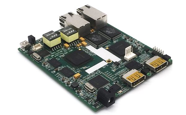
1, this set of weight tester has 4 half bridge weighing chips, 5 zigbee modules, 1 4G module, 4 button size NIMH batteries, 1 A/8 battery size NIMH batteries, a number of circuit plate composition
2, each weight sensor focus range of 10-150kg
3. Collect and transmit the data summary of each pressure gauge to the cloud server
4, the weight measuring device and the transceiver communicate with zigbee
5. Data transmission frequency: the communication frequency between the weighing device and the 4G receiver and transmitter is 10 minutes/time, and that between the 4G receiver and transmitter and the cloud is 2 hours/time
Weight measurement method:
I. Four weighing weight gauges are activated at the same time. If any one pressure gauge is not activated, it will be regarded as invalid weight measurement. The activation state is defined as the weight measured by a weight gauge greater than 10KG. If any weight gauge measures less than 10KG, the hoof of the cow may be in a state of incomplete strength and the value of this activation state may be adjusted during field tests
2, 4 weight measuring device measured and transmitted to the receiver and transmitter at the same time weight data, the receiver and transmitter judge as effective number drama and then sum up, and after the value as effective weight temporarily stored in the receiver and transmitter memory, when regular transmission, memory overflow automatically press FIFO to clear
Operation procedure when the instrument is turned on:
1. The motors of the five devices will be initialized. The 4G receiver and transmitter will connect with the four pressure sensors through zigbee communication to confirm the normal connection of the five devices.
2, test stage: After setting the number of samples to be weighed, the computer/mobile phone directly connected to the 4G receiver and sender click "Start" : immediately display the weight value of each pressure gauge, and there is a summary of the total weight value of superposition. Test values of individual weight meter and 4G receiver and transmitter can be tested during the test. In addition, 3/4 modules can be used to calibrate the pressure deviation values of each weight meter.
3. The communication between the weight sensor and the 4G receiver and transmitter is based on the IP address and MAC address for unique identification, which is also applicable to the communication with the cloud server
PCB design of automatic sampling equipment
1. The device drives the stepper motor driver through the single chip microcomputer, and the driving mode is to send pwm pulse.
2, through the MOS tube switch form control of DC motor
3. The strain type half-bridge weighing chip HX711 is used to weigh
4, through the photoelectric position sensor to obtain the position of the stepper motor
4. Complete the operation of man-machine interface in the form of Diwen serial screen

This instrument has a total of 6 motors:
No. 1: Sampling needle vertical motor (57 stepper motor)
No. 2: Sampling needle horizontal motor (42 step motor)
No.3: Disc rotating motor (57 stepper motor)
No.4: Sampling for peristaltic pump motor (42 step motor)
No. 5: Scale lifting motor (42 step motor)
No.6: Reagent added to peristaltic pump motor (42 step motor)
The other two diaphragms only need to control the switching time (cleaning and waste liquid extraction time).
Operation procedure when the instrument is turned on:
1. 6 motors will be initialized. The sampling needle on the rotating arm is automatically reset to the upper part of the cleaning pool (motor No. 1 and No. 2 action).
After all the reset work is completed, start to do the sample operation steps:
2. After setting the number of samples for this time, click "Start" : 1. The sampling needle on the rotating arm starts cleaning the needle (No. 1 motor action and two diaphragm pumps action); 2. The scale will rise automatically and weigh the samples (No. 5 motor action).
3. Put about 2g samples into the sample cup (the sample scale set by our instrument is between 1.8-3.0g) and put them on the scale. When the scale senses the sample weight within the normal range, the disk rotates one cup position (No. 3 motor action), then puts the next sample, then rotates one cup position, and so on, until the last sample is put in. The scale automatically drops to the original position (motor No. 5 action).
4. After the weighing is completed, the disk starts to rotate (motor No. 3 action), the first sample standard rotates to the position of the sampling needle, and the sampling liquid starts to be added (sample adding quantity is determined by the sample weight, 0.1g sample corresponds to 0.5ml sample liquid) (motor No. 6 action).
5. After all sample adding is completed, the disk starts to rotate clockwise and counterclockwise alternately (No. 3 motor action) for the purpose of "shock mixing". The oscillation time is 2-3 minutes.
6. After the shock is completed, rotate the first sample standard in the disk to the position of the sampling needle (No. 3 motor action), and sample according to it (take 2.5ml of liquid as fixed) (No. 1 and No. 2 motor action). After taking the sample liquid, rotate the sampling needle to the top of the cupola (No. 1 and No. 2 motor action). The first sample liquid is injected into the first colorimeter hole (motor No. 4 action). After the injection is completed, the sampling needle is rotated to the needle washing pool (motor No. 1 and motor No. 2 action) to clean the needle (motor No. 4 action and two diaphragm pumps action). After the cleaning is completed, the sampling needle will sample the second sample, and so on, until the last sample is extracted.
7. After extracting the last sample liquid, the disc is reset to the initial position (motor No. 3 action), waiting for the sample cup to be taken out manually.
Note: This instrument has 6 motors, 2 peristaltic pumps and 2 diaphragm pumps. One peristaltic pump is used to add the sample liquid, and the other peristaltic pump is used to connect the rotary arm, extract and inject the sample liquid. A diaphragm pump is used to extract the waste liquid (the liquid used to clean the sample needle) and a diaphragm pump to clean the needle.


