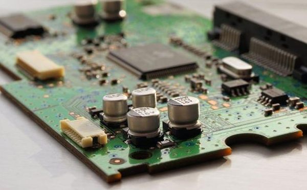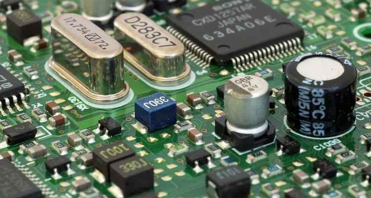
The important influence of PCB layout on printed boards determines the manufacturing, installation and later maintenance costs of printed boards to a certain extent. As electronic design tends to be high-density, PCB layout and wiring of each electronic product is particularly important. A good PCB layout design can often achieve a higher spread rate, reduce jumper distribution and electromagnetic interference between wires. Effectively reduce the generation of noise.
As with all new technologies, it took engineers a while to embrace and spread printed circuit boards .
But for years, PCBS seemed to be "relegated" to the realm of electronic engineering, the unsung heroes of behind-the-scenes efforts by managers who viewed PCB wiring as a trivial manufacturing problem, not the concern of design engineers; But as digital circuits became faster and RF circuits were incorporated into PCB, boards became the limiting factor in many designs. Computer-aided design (CAD) tools helped engineers design boards, but CAD's self-winding capabilities often created more problems.

Modern PCB are not only time killers, but also key components with precise design requirements; The frequency at which electronic devices operate, and the time at which signals rise and fall, is getting faster and faster, so PCB circuit boards have become increasingly important. Take a look at a few short stories that actually happened to give you some insight.
A story about the PC motherboard
In 1985, the 33MHz bus appeared in PC chipsets; Someone got a call from a local PC motherboard manufacturer saying their new motherboard wouldn't move. IC supplier's reference design can work, but this company made a customized product shape; And the guy noticed that they were winding the wires between the components, making the PCB run at a lot of sharp angles.
He also found that several key signals were placed in large loops and that there were many through-holes in the circuit boards; Those little holes allow the wiring to go from front to back of the board. The company says its PCB, designed by someone in Colorado, are cheap and quick, and can be finished in one or two days. The man politely told them that the wiring was done with automated software tools, so they would never be able to run a 33MHz circuit board successfully.
Automatic winding tools are easy to make mistakes, early PCB software can only ensure that the signal to the pin of the current connection, will not consider the high-speed signal needs a short line, the first layout of the required through hole, or because of the through hole, line width changes caused by impedance mismatch and so on, and finally lead to the failure of the entire PCB design.
A story about video chips
In 1995, an older brother was working for a video chip company and found himself in the same situation -- the reference design was fine, but a major customer in Taiwan complained that their chips wouldn't work on new PCBS. The PCB design had similar wiring errors.

The video chip company was faced with a choice between coming clean about the customer's design and asking them to redo it, or having their own video chip make a cheap metal mask modification to compensate for the customer's poor PCB boards wiring. They chose the second option, and of course the customer was happy, always right, and pleased with the customer service the video chip company sent them with new chips that worked.
'It's a smart strategy for a semiconductor company,' the older brother said. IC companies should import IP into their own chips, not pay to teach their customers how to design them. You can make changes in the chip and charge the customer in return.
A story about an F-16 fighter jet
Circuit board routing is considered a mechanical engineering task, so some electronics engineers throw out circuit diagrams and let other departments do the circuit board routing.
There were very high speed emission coupled logic (ECL) oscillators on the board, but the prototype 8-layer board did not work; With plenty of board floor space, I wonder how they messed up the design. It turned out that mechanical engineers arranged the components according to shape in order to simplify the design of the aluminum radiator underneath all the parts; The ECL chip is at the top left of the board, the resistor is in the middle, and the crystal oscillator is at the bottom right, eight inches away from the ECL chip.


