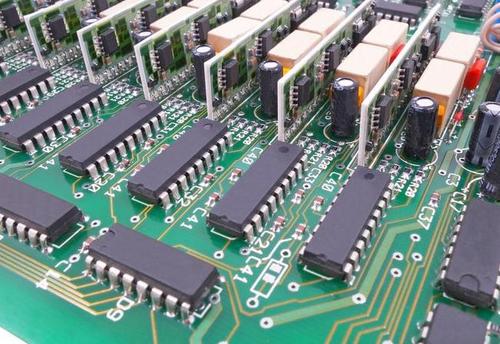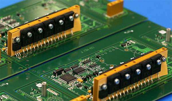
A typical soft and hard combined board is made of two groups of hard cover plate on the upper and lower surfaces of the circuit board, among which one or more layers of FPC is sandwiched in the middle. Generally speaking, the cover plate area of the soft and hard combined board is maintained as no line. The cover plate and FPC will be firmly attached together and extended to the hard zone, that is, the part containing PTH. Soft sheets may be attached to or separated from each other in areas where softness is required, depending on relative flexural requirements or manufacturing costs.
How is the soft - hard combination board defined
Most of the cover plate will not be made into a multi-layer structure in advance, but into a standard single-side line double copper panel, that is, when the multi-layer pressing is constructed with copper skin or cover plate pressing. The copper laminating method consists of constructing an external surface of a hard and soft bonded plate with a sheet of film on top. Cover pressing is similar to the general pressing process, but the original copper layer is replaced by a single-sided all-copper circuit board substrate. Both processes can be used in the traditional double copper cover plate process to deal with the singular layer or other structure of the soft and hard board process.
Before FPC stacking enters pressing, tool hole stamping, window opening, slotting and local forming of cover plate, soft board, film or bonding agent will be carried out first to produce non-sticking area or outer edge. These parts are more difficult to deal with the final hard and soft board.
The part of the window opening is made with a knife die, which aligns with the adhesive or film layer by means of tool holes and pins, and precisely cuts the specific area. The same process is used to produce a filling material of the same thickness as the adhesive, such as Teflon, Tedlar or TFe-glass cloth. However, most of the current processes used by the industry do not include fillers to save labor, but in the pressing process will be faced with fracture zone, junction thickness gradually thinning and tilt, unable to fully control the film flow problems. The caulk is the area extended into the window when stacked, and its function is:

1: Restore stack thickness to achieve uniform compression pressure
2: Avoid FPC interlayer bonding
3: Lock the adhesive (or film) flow
4: Keep distortions to a minimum
The cover plate is grooved along the edge of the area where the FPC needs to be exposed. If the cover plate is not grooved before pressing (or notched internally for disconnection), cutting this edge in the final product requires fairly dedicated and precise Z-axis control to avoid damaging the FPC.
The edge of the FPC layer may not be attached to the rest of the finished product, so it is very difficult to cut. Most of these parts will be cut locally in advance with a die. There will be no clear waste before pressing, and nothing will be clear. The FPC layer is introduced into the process as a single piece, and tool systems such as edges and edge areas are used to assist alignment and thickness control.
If the PTH region is actually required to produce a multi-segment structure, the sequential compaction process must be used. In this technique, the layers of the thinner areas are first completed and PTH processed before being imported into the final hard-soft board stack. At this time, the area where PTH has been completed is sealed inside the relatively thick soft and hard boards with extra soft and cover layers to establish the final thickness for the second PTH process.
The unattached part of the hard zone, if too large, may swell during plasma treatment and cause layer separation, depending on the overall sealing and the amount of free expandable matter contained. When the FPC bend zone is larger than 4 to 5 square inches, the expanding force generated in the hot, vacuum plasma process may pull open the edge of the cover plate. Faced with this situation, it is sometimes possible to make vent holes to release pressure in these areas, which may pull the edge of the cover. In this case, vents can sometimes be made to release pressure in these areas, but they must be sealed prior to the PTH process.
Flexible and rigid panels require particularly strict quality control. Perhaps the most challenging testing procedure is thermal stress, which may require a representative visual and sectional analysis of PTH test cuts. After baking at 125℃ for at least 6 hours, the test piece is cooled, fluxed and bleached at 288℃ for 10 seconds. After checking the surface defects such as: braided fiber abnormalities, fiber exposure, scratching, annular separation, dent, indentation, and then slice to analyze the overall condition of electroplating and the broad characteristics of the soft and hard areas.
It is customary to check the gasket and line area adjacent to the PTH hole first, and then check the extension along the line to the next PTH hole. A more common quality problem caused by the removal of hard and soft board is the extension of the substrate cavity, these are in the dielectric structure of the cavity or bubble, the general definition as long as the substrate cavity is greater than 3mil or interference to the space between conductors will be removed.
Some applications in the soft board area require very severe bending, and the gradient design can be used to reduce the stress in the standing state (but only after a very complex process and high stress welding assembly). Progression (Progression) is a design technique used in the FPC layer. Progression is a progression of bends from the inside out in the progression zone, which progressively increases to compensate for the increased length of the aisles.


