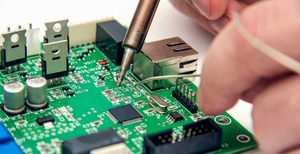
Sometimes the failure of components on PCBA board is the "death of components", and sometimes there is pressure but it is not obvious, so we feel that it is the failure for no reason, but we have not found the reason.
The "end of life" of devices is a cumulative decay effect resulting from physical or chemical changes.
Electrolytic capacitors and some types of thin-film capacitors are known to be "mortal" because of the chemical reactions that occur in their dielectric under the combined action of trace impurities (oxygen, etc.) and electrical pressure.
As IC structures follow Moore's Law and become smaller, doping migration at normal operating temperatures increases the risk that devices will fail in decades rather than centuries. In addition, magnetostrictive fatigue causes mechanical fatigue of inductors, which is a well-known effect. Some types of resistive materials oxidize slowly in air, accelerating as the air becomes more humid. Likewise, no one expects batteries to last forever.
Therefore, when selecting a device, it is necessary to understand its structure and possible age-related failure mechanisms; Even when devices are used under ideal conditions, these mechanisms may have an impact. Failure mechanisms will not be discussed in detail in this article, but most reputable manufacturers are concerned with the aging of their products and are usually familiar with working life and potential failure mechanisms. Many system manufacturers provide information on the safe working life of their products and their limiting mechanisms.
Under proper working conditions, however, most electronic devices can have a life expectancy of decades or more, but some still fail prematurely. The reason is often the stress of not being noticed.
Anyone designing electronics for use in the ocean has salt spray and humidity in mind -- and rightly so, because they're terrible! In fact, many electronic devices can encounter chemical challenges that are less scary, but still potentially harmful.
Electrostatic damage (ESD) is a stress mechanism, and warnings related to this are the most common, but we tend to ignore them.

When PCB circuit board are manufactured, adequate measures are taken to eliminate ESD during the manufacturing process, but after delivery, many PCBS are used in systems that do not have adequate protection against ESD caused by common operation. Adequate protection is easy, costs a little and is often overlooked. (Probably because of the bad economy). Assessing what ESD protection is required for system electronics under the most extreme circumstances of normal use and considering how to achieve it should be part of all designs.
Another factor is overpressure. Few people expect semiconductors or capacitors to survive major overvoltages, but it is common for large resistors to encounter voltages well beyond the absolute maximum listed in the data book. The problem: While its resistance is high enough not to get hot, it can generate tiny electric arcs inside, causing it to drift slowly off spec and eventually short circuit. Large wound resistors typically have breakdown voltages of hundreds of volts, so in the past this was not a common problem, but today it is widely used for small gauge resistors, whose breakdown voltage may be less than 30 V, and are quite susceptible to overvoltage.
High currents can also cause problems. Everyone is familiar with a common fuse -- a piece of wire that gets hot and blows if too much current flows through it, preventing short circuits and other similar problems. However, if you have a very high current density in a very small conductor, the conductor may not become very hot, but it may still fail eventually.
The reason is something called electromigration 3 (sometimes called ion migration). That is, the momentum transfer between conducting electrons and diffused metal atoms leads to the gradual movement of ions in the conductor, causing the material transport effect. This allows thin conductors carrying large DC currents to become thinner over time and eventually fail.
But some parts can fail like fuses, or blow out, like wires or the conductive wiring on semiconductor chip. A common reason for this is that the capacitor charge current is too high. Consider a 1 µF capacitor with an ESR of 1 Ω. If connected to a 110 V, 60 Hz AC power supply, about 41 mA of AC current will flow through it. However, if connected to an AC power supply at the maximum voltage (110√2 = 155.6V), only the ESR will limit the current and the peak current will reach 155.6A, although its duration is less than 1μs, which is enough to damage many small-signal semiconductor devices.
Repeated surges can damage the capacitor itself, especially electrolytic capacitors. This is a particularly common failure mechanism in cheap low-voltage switching power supplies (" wall adapters ") used to charge small electronic devices. If inserted at the wrong time of an AC cycle, the rectifier and capacitor can carry very large surge currents, which can eventually damage the device if repeated. Using a small resistor in series with the rectifier can limit this surge current and minimize the problem.
If we are very lucky, ESD or overvoltage/overcurrent events will damage the device immediately, so it is easy to know the problem. But more often, pressure-induced damage leads to device failure, long after the pressure that caused the failure in the first place has disappeared. It is difficult, if not impossible, to diagnose the cause of the failure of such PCBA.
Whatever circuit is designed, it is necessary to consider the working life and failure mechanism of the device used, and whether there are any potential problems or stressors that could cause the device to be damaged under the most extreme conditions of permitted use. Any such issues should be considered and minimized as much as possible in the final design.


