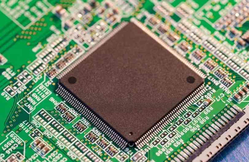
PCB board arrangement and reasonable layout:
(1) The printed circuit is not allowed to have a cross circuit, for the possible cross lines, you can use "drill", "wind" two ways to solve. That is, let a lead from other resistance, capacitance, the gap at the foot of the audion "drill" in the past, or from the possible cross of a lead end "wound" in the past, in special cases how to circuit is very complex, in order to simplify the design also allows the use of wire straddle, to solve the problem of cross circuit.
(2) Resistance, diode, tubular capacitor and other components have "vertical", "horizontal" two ways of installation. Vertical refers to the component body perpendicular to the circuit board installation, welding, its advantage is to save space, horizontal refers to the component body parallel and close to the circuit board installation, welding, its advantage is that the mechanical strength of the component installation is better. These two different mounting components, the component hole spacing on the printed circuit board is not the same.
(3) The ground point of the same level circuit should be as close as possible, and the power filter capacitor of this level circuit should also be connected to the ground point of the level. In particular, the base of the transistor, the emitter of the ground point can not be too far away, otherwise because the copper foil between the two ground points is too long will cause interference and self-excitation, the use of such a "point grounding method" circuit, the work is more stable, not easy to self-excitation.
(4) the total ground wire must be strictly in accordance with the high frequency - medium frequency - low frequency one level according to the order of weak current to strong current principle, must not randomly turn over and over, between the level would rather wiring long point, also want to comply with this provision. In particular, frequency conversion head, regeneration head, frequency modulation head grounding wire arrangement requirements are more strict, if there is improper will produce self-excitation so that it can not work.

In order to ensure a good shielding effect, a large area enclosed ground wire is often used in the high frequency circuit of FM.
(5) The strong current lead (public ground wire, power amplifier power lead, etc.) should be as wide as possible to reduce the wiring resistance and voltage drop, can reduce the self-excitation caused by parasitic coupling.
(6) The high impedance of the line as short as possible, low impedance of the line can be longer, because the high impedance of the line is easy to whistle and absorb signals, causing circuit instability. The power line, ground wire, base wiring and emitter lead of non-feedback components are all low-impedance wiring. The ground wire of the base wiring of emitter follower and the ground wire of the two sound channels of the radio and recording machine must be separated into one road and then combined until the end of the effect. If the two ground wires are connected, crosstalk is easily generated and the separation degree is reduced.
Design of hybrid PCB boards for PCB design company
For modern board design, the concept of hybrid PCB boards is ambiguous because even in purely "digital" devices, there are still analog circuits and analog effects. Therefore, at the initial stage of design, simulation effect must be carried out in order to realize strict timing allocation reliably. In fact, in addition to the fact that communication products must have the reliability to work without failure for several years, simulation effects are particularly required in mass-produced low-cost/high-performance consumer products.
1. Basic wiring of mixed signal circuit
When digital and analog circuits share the same components on the same board, the circuit layout and wiring must be methodical. The matrix shown in Figure 1 is helpful for the design and planning of mixed-signal PCB. Only by revealing the characteristics of digital and analog circuits can the desired PCB design objectives be achieved in actual layout and wiring.
In mixed-signal PCB design, there are special requirements for power wiring and the isolation of analog and digital noise from each other to avoid noise coupling, thus increasing the complexity of layout and wiring. The special requirements for power transmission lines and the need to isolate noise coupling between analog and digital circuits add further complexity to the layout and wiring of mixed-signal PCBS.
If the power supply of the analog amplifier in A/D converter and the digital power supply of A/D converter are connected together, it is likely to cause the interaction of the analog part and the digital part of the circuit. Perhaps, because of the position of the input/output connectors, the layout plan must mix the wiring of the digital and analog circuits.
Before the layout and wiring, the engineer should understand the basic weaknesses of the layout and wiring scheme. Even in the presence of false judgments, most engineers tend to use layout and wiring information to identify potential electrical effects.
Ii. Layout and wiring of modern mixed-signal PCB
The design of OC48 interface card will explain the mixed signal PCB layout and wiring technology. OC48 stands for optical carrier Standard 48, basically for 2.5Gb serial optical communication, it is a high capacity optical communication standard in modern communication equipment. The OC48 interface card contains several typical mixed-signal PCB layout and wiring problems. The layout and wiring process will indicate the sequence and steps to solve the mixed-signal PCB layout solution.


