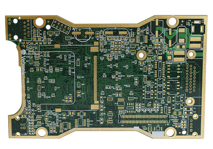
Energy storage battery PCBA management system
1. Detailed technical plan
The battery energy storage system consists of an energy storage battery, a master controller unit (BAMS), a single battery management unit (BMU), and a battery pack control and management unit (BCMU).
2. Internal communication of the energy storage system
2.1 Communication between energy storage BMS and EMS
BAMS uses a 7-inch display to display the relevant information of the entire PCS battery pack unit, and transmits the relevant information to the monitoring system EMS through Ethernet (RJ45). The information content includes battery cell information, battery pack information, and battery cluster information.
Upload information: BMS uploads battery cell (or group) information including: cell voltage, battery pack voltage, charge and discharge current, cell maximum SOC, cell minimum SOC, cell minimum SOH; battery pack SOC, cell maximum temperature, minimum cell temperature, ambient temperature, and related information such as battery abnormality alarms and protections.
Receiving information: BMS receives the battery operating parameters issued by the monitoring system EMS, such as voltage protection setting value, alarm setting value, temperature protection setting value, alarm setting value, SOC protection setting value, alarm setting value wait.
BAMS management server supports MODBUS communication protocol, in which MODBUS needs to define a special protocol point table; the communication interface is network RJ45 communication.
2.2 Communication between energy storage BMS and PCS
Since the PCS is only connected to multiple sets of batteries, the data of the BMS is aggregated to the BAMS, and then the BAMS communicates with the PCS for one-way transmission. The BAMS is the master and the PCS is the slave.
Information sent by BMS: The information sent by BMS includes related information such as battery state quantity and alarm quantity. Including the maximum SOC of the battery pack, the minimum SOC, the maximum chargeable capacity of the battery pack, the maximum dischargeable capacity of the battery pack, the ambient temperature, the minimum SOH of the battery, etc. PCS should take corresponding protection actions after receiving BMS alarm information.
Communication interface: CAN or RS485 communication interface is used between PCS and BMS.
Hard node information: For timely and reliable protection, the energy storage system has reserved hard nodes. When the BMS detects that the battery system has reached the protection limit, the BMS sends the protection limit value to the PCS through the dry node.
2.3 Internal communication of energy storage BMS three-tier architecture
The three-layer architecture of the BMS system is the single battery management BMU, the battery pack management BCMU, and the battery cluster (multi-group) management BAMS; among them, the battery cluster management is also called a PCS battery unit management.
Figure 1 Internal communication diagram of energy storage BMS three-tier architecture
The single battery management layer is called BMU, which has 1 CAN2.0 bus. Composed of a battery acquisition unit BCU and a battery equalization unit BEU, it collects various cell information (voltage, temperature) of the battery, calculates and analyzes the SOC and SOH of the battery, realizes active balancing of the cell, and uploads the abnormal information of the cell For the battery pack unit layer BCMU; externally adopts CAN2.0 bus communication mode.
The management team of the battery pack is called BCMU, which has 3 CAN2.0 buses and 2 RS485 (standby) buses. Responsible for collecting various single battery information uploaded by the BMU, collecting various information of the battery pack (pack voltage, pack temperature), battery pack charging and discharging current, etc., calculating and analyzing the SOC and SOH of the battery pack, and uploading all information to the battery Cluster unit layer BAMS; CAN2.0 bus communication mode is adopted.
The management layer of the battery cluster is called BAMS, which has 1 Ethernet, 2 CAN2.0 buses and 1 RS485 (standby) bus. Responsible for collecting various battery information uploaded by BCMU, and uploading all information to the energy storage monitoring EMS system through the RJ45 interface; communicating with the PCS, sending the relevant abnormal information of the battery to the PCS (CAN or RS485 interface), and equipped with hardware dry Node to PCS.
2.4 Equalization function of BMS system
The BMS of the battery energy storage system should focus on two aspects, one is the data analysis and calculation of the battery, and the other is the balance of the battery. The battery management system provided by the energy storage power station has a two-way active non-destructive equalization function, with a maximum equalization current of 5A and an equalization efficiency of over 80%. The consistency of the battery pack improves the efficiency and service life of the battery pack and ensures the normal operation of the entire energy storage system.
Single battery balancing unit:
Due to the production process and other reasons of the single battery, the capacity and performance of each battery are different. In the process of charging and discharging the battery pack, this difference will inevitably be enlarged. When charging, the battery with small capacity and poor performance will be overcharged; When discharging, the battery with small capacity and poor performance will be over-discharged; the capacity utilization rate of the battery pack will be lower and lower. If things go on like this, this vicious cycle process will accelerate the damage of the battery. Therefore, it is the consensus of scholars and industries at home and abroad that power and energy storage battery packs need to use a balancing circuit to prolong the life of the battery pack.
Figure 2 Schematic diagram of battery balancing function implementation
The balance system of the battery monitoring module mainly includes four steps: battery information collection→balance rule calculation→balance state output→balance realization.
2.5 Three-level architecture module and installation introduction of energy storage BMS system
2.5.1 Energy storage system management unit BAMS
BAMS is a platform built by a high-performance 32-bit MCU processor, embedded with a Linux operating system, and comes with a 7-inch TFT touch LCD display. It can upload the data of the lithium battery energy storage system to the background management in real time, and can accept background monitoring; independent research and development , support function expansion and customized services, BAMS and microgrid central control system use Ethernet ModbusTCP/IP as the communication method, and PCS communication interface as RS-485, the protocol method uses Modbus; Real-time monitoring and data management of the energy system to achieve remote measurement, remote signaling, and remote control, so that the energy storage system can be maintained in a timely manner, ensure the safe operation of the energy storage system, and improve the reliability of the power supply system.
Figure 3 interface
BAMS performs real-time display, data calculation, performance analysis, alarm protection and other processing through the real-time battery data uploaded by BCMU, and realizes linkage control with PCS and energy storage monitoring background system (EMS). According to the output power requirements and the SOC of each battery group Optimize the load control strategy to ensure the optimization of all battery packs.
The main controller of the energy system monitors the voltage of the single battery, the terminal voltage of the battery group, the charging and discharging current and the temperature online, and according to the SOC, voltage, temperature, battery voltage, temperature, charging and discharging of each single battery uploaded by the BCMU Current and various abnormal alarm information are displayed. Real-time monitoring and data management of the lithium battery energy storage system can be carried out through the remote server via the Ethernet to realize telemetry, remote signaling, and remote control, so that the energy storage system can be maintained in time to ensure the safe operation and reliability of the energy storage system; reserved The dry node communicates with the PCS to ensure that the battery system communicates with the PCS under abnormal conditions.
Table 1 Technical indicators of energy storage system management unit (BAMS)
2.5.2 Single battery management module BMU-L3216
The energy storage single battery management BMU_L3216 module adopts advanced measurement technology to accurately measure battery parameters in real time, such as voltage, current, temperature and other data, and upload the measured data to the energy storage system management unit.
The main functions of the energy storage battery management module
Ø Online automatic detection of single battery voltage, temperature, etc.;
Ø Online 2A lossless equalization can realize charge equalization;
Ø Real-time alarm function to realize over-limit alarm for voltage and temperature;
Ø On-site alarm, the dry node output is closed, and the remote computer alarm can be realized and the alarm content can be displayed;
Ø With RS485 communication interface, it can be connected to the monitoring system or on-site acquisition unit to realize the sending of data and alarm information, and achieve the purpose of remote monitoring of the battery pack;
Ø Modular design is adopted, the modules are isolated from each other, and the system reliability is high.
The main indicators of the energy storage battery management module:
Module power supply voltage: DC 24V±10%
Number of battery monitoring sections: 16 sections
Voltage detection range: 0 ~ 5.0 V
Voltage detection accuracy: ±0.1%FSR
Temperature measurement accuracy: ±1°C
Lossless equalization current: 2A
Battery equalization method: Active non-destructive charge equalization
Input insulation resistance: ≥5MΩ 500V
Data communication interface: RS485 or CAN2.0
Communication baud rate: 9600bps or 250kbps
On-site display mode: LED working status indication
Size and quality: 250×126×45(mm)/1Kg
Installation method: rack, wall
(A) Description of the working principle of the equalization system:
u Battery information collection:
Fast and accurate battery information collection is the basis for effective equalization; the energy storage battery management module uses a high-speed, high-precision, high-effective-bit Σ-Δ 24-bit AD converter, and high-precision (±0.05%) low-temperature drift (± 2PPM) to ensure high consistency and accuracy of battery information measurement under any permissible working environment.

u Balance rule operation:
The balance rule is to pick out which batteries need to be balanced and how to balance them. The operation of superior balance rules is the guarantee of effective balance. The balance rule of the energy storage battery management module integrates relevant factors such as battery pack status, battery voltage, battery SOC, temperature, battery manufacturer, cycle times, etc., so that the calculation results are more in line with actual needs, and can realize discharge, charge and dynamic balance.


