
Professional PCB manufacturing and assembly
Building 6, Zone 3, Yuekang Road,Bao'an District, Shenzhen, China
+86-13923401642Mon.-Sat.08:00-20:00

SMT Assembly Packaging and Machine Test Program
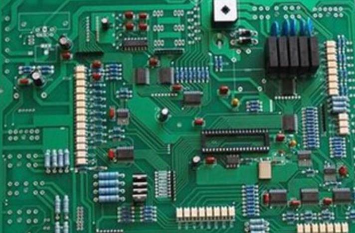
Surface mount components of various packaging sizes
SMT processing plants usually have some common knowledge about SMT processing. As the person who is most familiar with SMT, SMT factory is undoubtedly the person who has the most say. Today, we will focus on the package size of surface mount components, which I hope will be helpful to you.
There are 9 kinds of common SMT chip resistor packages, which are represented by two size codes. Single code is EIA code represented by 4 bits. The first two digits and the last two digits represent the length and width of the resistor, organized in inches. We often say 0603. Package refers to inch code. The other is metric code, which is also represented by 4 bits and is organized in millimeters. The following table lists the relationship between inch and metric package of chip resistor package and detailed size: for example, 0.12.7mm (5 mil) thick step laser cutting electrolytic polishing model is used to meet the requirements of solder paste screen printing on the circuit board. Because the release characteristics of solder paste are not clear, some pad designs include holes in the pad, and their determination depends entirely on the traditional template design experiment. In this case, all holes of 0201 equipment are designed to have a ratio of 1:1 between holes and pads.

Since there are other components on the PCB, including CCGA equipment, the 0.127mm (5 mil) thick template may be the thinnest template. Stepstencil is not designed to prevent damage to solder joints of other components on the circuit board. The aspect ratio of the design is between 2.4 and 3.2. The area aspect ratio ranges from 0.72 to 0.85. Based on these values, a good solder paste release effect can be predicted.
Surface mounted patch processing machine test steps
What are the requests and test procedures for SMT processing? In contrast, this is a big problem for many novices in the SMT processing industry. Next, Jingbang Technology will analyze the process and the number of jobs in the process for you, hoping to help and inspire you.
1. Encoder test:
Preparation: prepare a modulator, a program source (such as DVD), a satellite receiver (for receiving modulator signals), a TV set, 3 video cables, S-video cables and audio cables, coded sulfur data cables (dual Q9 cables), and RF cables (L16 to head F).
Test steps for surface mount patch processing:
A. Connect various data cables and power cables, open and check whether the display screen is normal.
B. To operate the keyboard, first set the encoder to the default setting.
C. Check the image effect on the TV to see if the image is normal
D. Use a hair dryer to slowly heat the encoder and observe whether the image is normal.
E. Knock the encoder by hand and observe whether the image is normal.
F. Repeat power on and power off several times to check whether the encoder works normally.
G. Interface check: replace it with a different data interface to check.
Note: Please refer to the product operation manual for the specific operation methods involved in the above operation process, and check the functions shown in the manual accordingly.
End of test: during the above inspection process, the image and sound have been smooth, and the equipment is qualified.
2. Surface mounting patch processing multiplexer test:
Preparation: prepare the modulator, encoder, program source (such as DVD), satellite receiver (for receiving the modulator signal), TV and two streaming data cables, video cable, audio cable, (dual Q9 cable), and RF cable (L16 to F head).
Test steps:
A. Connect various data cables and power cables, turn on the computer, and check whether the monitor is normal.
B. To operate the keyboard, first call the default settings of the multiplexer once.
C. Check the image effect on the TV to see if the image is normal.
D. Use a hair dryer to slowly heat the multiplexer and observe whether the image is normal.
E. Knock the multiplexer by hand and observe whether the image is normal.
F. Repeated power on and power off for several times to check whether the multiplexer works normally.
G. Interface check: replace it with a different data interface to check.
Note: Please refer to the product operation manual for specific operation methods involved in the above operation process
End of test: during the above inspection, the image and sound have been smooth, and the equipment is qualified
3. Surface mounting patch treatment module test:
Preparation: a spectrum analyzer, an encoder, a program source (such as DVD), a satellite receiver (for receiving modulator signals), a TV, streaming data cable, video cable, audio cable (dual Q9 lines), RF cable (L16 to F head and dual L16).
The above is the explanation given by the editor of pcb circuit board company.
If you want to know more about PCBA, you can go to our company's home page to learn about it.
In addition, our company also sells various circuit boards,
High frequency circuit board and SMT chip are waiting for your presence again.
SMT processing equipment and inspection items
Dec 28,2022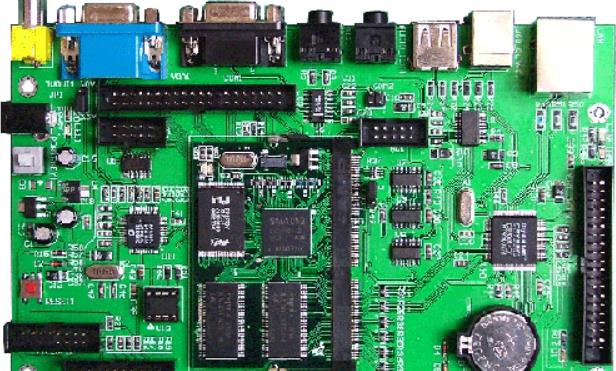


Telegram
Just upload Gerber files, BOM files and design files, and the KINGFORD team will provide a complete quotation within 24h.