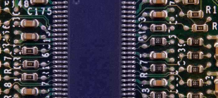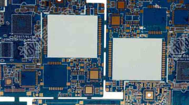
The wiring switching power supply contains high-frequency signals. Any printed line on the PCB can play the role of antenna. The length and width of the printed line will affect its impedance and inductive reactance, thus affecting the frequency response. Even printed lines that pass through the DC signal can couple from neighboring printed lines to the RF signal and cause circuit problems (or even re-radiate interference signals). All printed wires that pass through the AC current should therefore be designed to be as short and wide as possible, which means that all components connected to the printed wires and to other power lines must be placed close together. The length of the printed line is proportional to its inductance and impedance, and the width is inversely proportional to the inductance and impedance of the printed line. The length reflects the wavelength of the printed line's response. The longer the length, the lower the frequency at which the printed line can send and receive electromagnetic waves, and the more radio-frequency energy it can radiate. According to the size of the printed circuit board current, try to rent the width of the power line, reduce the loop resistance.
At the same time, make the direction of the power line, ground line and the direction of the current, which helps to enhance the anti-noise ability. Grounding is the bottom branch of the four current circuits of the switching power supply. As the common reference point of the circuit, it plays an important role. It is an important method to control interference. Therefore, careful consideration should be given to the placement of ground wires in the layout. Mixing all kinds of ground will cause unstable power supply. The following points should be noted in the design of ground wire:
1, the correct choice of single point grounding usually, the common end of the filter capacitor should be the only connection point of other ground points coupled to the AC ground of large current, the ground point of the same level circuit should be as close as possible, and the power filter capacitor of the circuit should also be connected to the ground point of the level, mainly considering that the current of each part of the circuit back to the ground is changed. Interference is introduced due to the impedance of the actual flowing line, which causes changes in the ground potential of various parts of the circuit. In this switching power supply, the inductance between wiring and components has little influence, while the circulation formed by grounding circuit has great influence on interference. Therefore, one-point grounding is adopted, that is, ground wires of several devices in the power switching current loop () are connected to the ground pin, and ground wires of several devices in the output rectifier current loop are also connected to the ground pin of the corresponding filter capacitor. This power supply work more stable, not easy to self-excitation. When you can't do a single point, you can connect two diodes or a small resistor at a common location. In fact, you can connect it to a concentrated piece of copper foil.

2, as far as possible coarse grounding wire if the grounding wire is very fine, grounding potential changes with the change of current, resulting in electronic equipment timing signal level instability, noise resistance performance deteriorated, so to ensure that each large current grounding terminal using as short and wide printed wire, as far as possible to widen the width of the power supply, ground wire, it is best to ground wire wider than the power line, their relationship is: ground wire > Power cord > Signal wire, if possible, the width of the ground wire should be greater than 3mm, can also be used as a large area of copper layer ground, on the printed board is not used to connect with the ground as ground. When conducting global wiring, the following principles must be followed:
(1), wiring direction: from the welding surface, the component arrangement orientation should be consistent with the schematic diagram as far as possible, and the wiring direction should be consistent with the wiring direction of the circuit diagram. Because the production process usually requires various parameters detection on the welding surface, it is convenient to do so in the production inspection. Debugging and maintenance (Note: on the premise of meeting the requirements of circuit performance, overall installation and panel layout).
(2), the design of wiring diagram, as little as possible to turn the line, printing arc on the line width do not change, wire corner should be more than 90 degrees, and strive to simple and clear lines.
(3) Cross circuit is not allowed in the printed circuit, for the possible cross lines, you can use "drill", "wind" two ways to solve. That is, let a lead from other resistance, capacitance, the gap at the foot of the audion "drill" in the past, or from the possible cross of a lead end "wound" in the past, in special cases how to circuit is very complex, in order to simplify the design also allows the use of wire straddle, to solve the problem of cross circuit. Because of the single panel, the in-line component is located on the top surface and the surface paste device is located on the bottom surface, so in the layout of the in-line component and the surface paste device overlap, but to avoid the overlap of the pad.
3, the input ground and the output ground in the switching power supply for low-voltage DC-DC, to feedback the output voltage back to the primary transformer, the circuit on both sides should have a common reference ground, so after the ground wire on both sides of the copper, but also connected together, to form a common ground.
After the wiring design is completed, it is necessary to carefully check whether the wiring design conforms to the rules formulated by the designer, and also confirm whether the rules formulated meet the requirements of the printed board production process. Generally, it is necessary to check whether the distance between wire and wire, wire and component pad, wire and through hole, component pad and through hole, through hole and through hole is reasonable, and whether it meets the production requirements. Is the width of the power cord and ground wire appropriate? Is there any place in the PCB where the ground wire can be widened? Note: Some errors can be ignored. For example, some connectors have part of their Outline lying outside the frame, and errors occur when checking spacing. In addition, after each modification of the line and hole, it is necessary to re-cover the copper once.
Vi. Review According to the "PCB checklist", the content includes the design rules, layer definition, wire width, spacing, pad, hole setting, but also focus on the review of the rationality of the device layout, power supply, ground network wiring, high-speed clock network wiring and shielding, the placement and connection of the coupling capacitor.


