Military Grade Electronics PCB Design Considerations
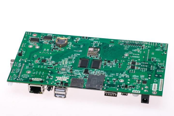
Military toughness is one size fits all. Not just the hardened personnel, but the electronics and computers used in the field. Of course, this means that the printed circuit boards (PCBs) used in defense need to be as tough as nails.
While designing commercial PCBs is no easy feat, designing and manufacturing military-grade PCBs requires special attention to durability and compliance. All components must be able to withstand the harsh environment. Requirements for military-grade electronic PCBs include:
Minimal tolerances (between 1-2%) compared to 5-10% for commercial grade electronic PCBs.
Expected 5 – 15 year increase in product life
Ability to handle extreme conditions
Rigorous and specific design and layout techniques
Higher Reliability, Stronger, Stronger
Achieving each of these conditions requires adequate preparation and consideration from the design stage.
To gain insight into the importance of using military-grade PCBs correctly, here are some applications that rely on military-grade PCBs:
Base and Camp Protection and Security Systems
Unmanned vehicles, military artillery and mortars
robot system
ruggedized computer
Defense Navigation and Communications Systems
Satellite Subsystem Using Embedded Processor
OEM engineers working on military-grade electronic designs need a solid understanding of the design considerations critical to reliability and high-quality performance.
General Design Considerations for Military-Grade Electronics
All PCBs falling into this category should meet MIL specification level standards and pass the highest performance and functional tests. General considerations for military PCBs include:
A military-grade PCB should handle the maximum current load.
There should be a clear distinction between low frequency and high frequency components. For example, certain high-frequency components may produce waveforms that affect low-frequency components. These waveforms add noise and degrade signal quality. For the military, this is unacceptable.
All clock signals should be clean and shielded.
For smooth current transfer, all PCB traces should maintain a 45° angle or less.
Finally, all military-grade PCBs should be manufactured in strict accordance with MIL-PRF-50884, MIL-PRF-55110, and MIL-PRF-31032.
Material
After becoming familiar with the design requirements, you should also consider the best type of PCB substrate for designing and manufacturing military-grade electronic PCBs.
Only the best quality and heat-resistant materials are placed on the table. Military-grade electronics are often used in harsh conditions, including high temperatures. Even under these conditions, the PCB should withstand and perform at a high level.
If heat dissipation is required, thermal paste should be used. Decoration materials should also be carefully considered. They should support the operation of the PCB under harsh environmental conditions.
High-quality materials that can withstand extreme weather and temperatures are a must. At this stage, an in-depth understanding of the different composite materials, substrates and elements used in the PCB is invaluable.
They must meet specific rigidity, flexibility, electrical and thermal requirements to be considered military grade. Some of the best materials for military PCB boards are:
 aluminum
copper
High temperature laminate
In some cases, anodized aluminum is also used to minimize the effects of thermally induced oxidation.
Coating and Surface Treatment
The military has specific requirements for surface treatments to protect PCBs from harsh environmental conditions, including dust, water, vibration, and extreme temperatures. Therefore, coatings and surface treatments are important features of military-grade electronics. The copper coating protects the PCB from rust.
Depending on the function of the PCB, a variety of surface finish materials are available:
Hot Air Solder Leveling (HASL)
Electrolytic Wire Bonding Alloy
sinking silver
Lead-free HASL
Electrolytic Nickel and Gold
Electroless Nickel with Immersion Gold Coating
Acrylic or acid-based sprays can also be used for conformal coating of PCBs to further protect them from weather and other external elements.
durability
Durability and reliability are major concerns for the military. What's more, these components are used in less than ideal conditions and can be damaged by damage such as solder cracking.
On average, military electronics have a service life of 5 to 15 years, ensuring durability, reliability and longevity, minimizing vibrations from installed components.
For many military PCBs, through-hole mounting is the recommended mounting method during PCB assembly. Boards made using this technique are extremely durable. Additionally, the method utilizes soldering on the top and bottom of the board to create a strong physical connection between the component and the board.
PCB Test Methods and Precautions
Thorough testing is essential to confirm the reliability and durability of a PCB in real-world applications. For military PCBs, the MIL-STD-202 standard is the basis for all electronic product test methods.
After the PCB has been designed to meet manufacturability considerations, various tests can be performed, including:
X-Ray Inspection – Also known as AXI, this test checks for defects such as solder connections, barrels, and internal traces before a PCB goes into full manufacturing.
Functional Test - The ancient functional test checks that the PCB will power up. How functional testing is performed depends on the application.
Military PCBs can also undergo a variety of other tests, including:
Solderability Test
PCB contamination test
Time domain reflectometer (high frequency board)
Float test
MIL-STD/ITAR/NADCAP: Understanding the different certifications and their applications
MIL-STD, ITAR, NADCAP...it's easy to get lost in the alphabet soup of military, defense and aerospace certifications.
Many OEMs often confuse each other, thinking that only one certification is sufficient, rather than all three.
To help you understand the differences and why all three criteria are important, here is a brief overview of each:
Military standard:
The MIL-STD standard covers the final characteristics of the product, as well as the production process, materials and safety standards. MIL-STD includes five types of defense standards:
interface standard
design standards
Manufacturing process standard
standard practice
Test method standard
These defense standards are designed to ensure the proper performance and logistical utility of military equipment.
ITARs:
The ITAR standard focuses on military equipment and sensitive information that may involve military equipment. The number of aspects of product development that are subject to ITAR regulations are numerous - some obvious but not so obvious:
design information
development information
Production Process
manufacturing steps
Assembly drawing
Repair Procedures for Specific Components
test protocol
Revise
Quality electronics contract manufacturers should pre-verify ITAR compliance as part of the quoting process. In this way, it ensures that everyone involved in the process adheres to the ITAR compliance checklist.
Nadcap:
Nadcap is an accreditation program for companies in aerospace-related industries. Nadcap accreditation is awarded at the company level for specific processes such as:
coating
chemical processing
heat treatment
conventional processing
welding
non-destructive testing
These standards often work together. Typically, some technology produced under MIL-STD compliance will be exported under ITAR regulations. Nadcap accreditation comes into play during construction such as heat treating, coating and more.
For MIL-STD rated electronics, ensuring your electronics contract manufacturer has the latest MIL-STD, ITAR and Nadcap certifications will ensure your PCBs are suitable for all military grade applications and sales.


