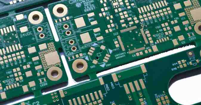
Functional testing is often used to calibrate or verify analog circuits, including checking the inside of the UUT (such as the IF portion of an RF circuit) to verify its operation, which may require test points or test pads. One of the problems with high frequency design is that the relative impedance of the test point (path length, test pad size, etc.) plus the impedance of the probe will affect the performance of the circuit, which should be kept in mind when setting up the test area, while the automatic mechanical probe and needle bed fixture (discussed later in this article) only require a smaller test area, which can alleviate this conflict, mainly because compared with manual operation, The accuracy of the automatic mechanism itself allows the tester to detect a smaller area.
Fault diagnosis
If you are only using functional tests as a pass/fail filter and do not need to measure calibration points, you can skip this section because the application may not need to use probes at this time. In most cases, functional tests perform pass/fail checks because functional tests are very slow in diagnosing faults, especially in the case of multiple failures. However, in some industries, functional testing is going deeper into the manufacturing process, such as cellular phone manufacturing, and some manufacturers have to perform some key measurements at the PCB level, that is, during the assembly process before final assembly, which is determined by the easily obsolete nature of the mobile phone. In other words, phones are designed to be assembled at a low cost, and they are not easy to disassemble, so verifying features before final testing saves on rework costs and reduces potential scrap (because phones can be damaged when taken apart).

Therefore, to probe the PCB, there needs to be sufficient test points, such as checking the J-lead of a surface mount device with a pitch of 20mil is not very convenient, and BGA is not possible. According to the American Surface Mounting Technology Association (SMTA), the minimum test point spacing is 0.040 inches, the spacing between pads depends on the height of the components around the test area, probe size, etc., but 0.200 inches should be the minimum requirement, especially for manual exploration areas. Obviously, test fixtures and automatic mechanical probes are more accurate.
Test design
It goes without saying that a design that is easy to test is easier to work with in production than a design that is arbitrary. However, engineers often want to pack more technology into the smallest volume at the lowest cost, which increases the limit of contact with the board in online and functional testing.
The market is also responding to these problems, and software tools are now available that analyze designs, review them against the rules specified in assembly and test equipment, and make recommendations to make PCBS easier to produce. If these tools are applicable to your product, it is recommended to analyze each design, at least it will quickly point out where test contact problems have been found, with the ultimate goal of making the product easier to manufacture.
Structural configuration to meet the requirements of high density
High density can be a small PCB size, or a large number of circuits on the UUT, or both, and the above headings indicate that the mechanical and electrical structure of the system must be considered to meet the requirements of the test. Mechanical considerations include:
How do I support UUT
Test area
Multilayer board testing (Can the tester do parallel testing?)
I/O connector
In electrical terms, if it is multi-layer board, then which is more economical? Is it a multi-instrument approach or a switch converter with a few instruments? Depending on the UUT structure or the type of instrument required, the answer may not be easy to come up with.
Automated or manual testing?
As the output and speed of each production line increases (a major way to achieve economies of scale is to increase the productivity of each test device), you should consider whether you can automate the test process. Automated functional testing actually eliminates load/unload time, does not require additional test systems, and often does not take into account the increased cost of transport equipment when considering increased production.
The drawbacks of test automation include having an initial hardware investment, time to integrate with the production line, whether the test system can keep pace with the production line speed, and problems with production if the equipment fails. The offline tester does not directly affect the assembly line, and if the tester fails, the product can be taken off the production line and put aside to continue production, so that the production line will not be affected, but processing time and labor are also issues.
It should be borne in mind that manual testing may often involve the connection of a UUT with several cables and connectors, which generally have a lower service life than the probes on the needle bed jig and should therefore be included in the maintenance plan, which can reduce occasional failures.


