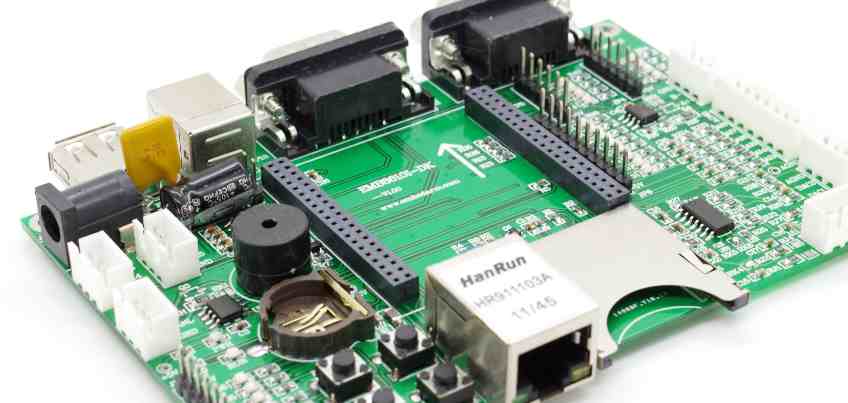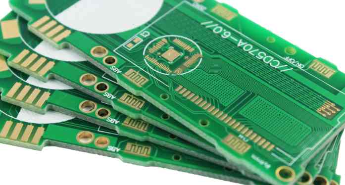
Integrated circuitmaintenance is a huge project, because the integrated circuit pins are many and very dense, it is very difficult to disassemble, and even sometimes damage the integrated circuit and circuit board. Hongyunlai Electronics with their own years of experience summed up several effective integrated circuit disassembly methods for your reference.
1, multi-strand copper wire tin suction disassembly method:
It is the use of multiple strands of copper core plastic wire, remove the plastic skin, and use multiple strands of copper core wire (short wire can be used). Before use, the multiple strands of copper core wire are coated with rosin alcohol solution, and after the electric soldering iron is heated, the multiple strands of copper core wire are heated on the integrated block pin, so that the solder on the pin will be adsorbed by the copper wire, and the part that absorbs the solder can be cut off. Repeat several times to absorb all the solder on the pin. Braided wire in shielded wire can also be used if possible. As long as the solder is sucked up and gently pry with tweezers or a small "one" screwdriver, the integrated block can be removed.

2, suction tin disassembly method:
Disassemble the integrated block using a tin absorber, which is a common professional method, using a common suction and welding dual-purpose electric soldering iron with a power of more than 35W. When removing the integrated block, just place the heated dual-purpose electric soldering iron tip on the integrated block pin to be removed. After the solder joint is melted, it is sucked into the fine tin device. After the solder of all the pins is absorbed, the integrated block can be removed.
3, increase the solder melting disassembly method:
This method is a hassle-saving method, as long as some solder is added to the pins of the integrated block to be removed, so that the solder joints of each column of pins are connected, so as to facilitate heat transfer and facilitate disassembly. When disassembling, use a soldering iron to heat each row of pins with pointed tweezers or a small "one" screwdriver to pry a pry, and the two rows of pins are heated alternately until they are removed. Under normal circumstances, each column of pins can be removed by heating twice.
4, medical hollow needle disassembly method:
Take a few hollow medical 8 to 12 needles. When in use, the inner warp of the needle is just over the pin of the integrated block. Disassemble the pin solder with the soldering iron, put the needle over the pin in time, then remove the soldering iron and rotate the needle, and pull out the needle after the solder solidifies. This makes the pin completely separate from the printed board. Once all the pins have been done this way, the block can be easily removed.
5, electric soldering iron brush with disassembly method:
The method is simple and easy, as long as you have a soldering iron and a small brush. When removing the integrated block, heat the electric iron first, and when it reaches the dissolving temperature, the solder on the pin is melted, and then brush away the melted solder. This allows the pin of the block to be separated from the printed board. The method can be carried out separately or separately. Finally, pry off the block with pointed tweezers or a small "one" screwdriver.
The reason why the red glue in the production of PCB circuit board falls off during over-wave soldering
In the PCBled circuit board production process, many electronics companies will use the red glue process to make SMT processes. In the process of using the red glue process, various components will encounter the problem of falling off, especially in the red glue process in the wave soldering process, the electronic component patch (especially the diode) often encounter the problem of falling off.
A detailed solution is given for the causes and solutions of over-wave soldering of components in the red glue process, as follows:
First, the PCB after the tin patch element drops
1. If the patch component and BCB's green oil (solder oil) fall off together, I will judge the PCB's incoming material problem (the adhesion of green oil is not enough).
2. Look at the PCB to see if there is scratch where the patch element falls off. Scratch where the PCB patch element falls off will also make the adhesion of the green oil insufficient, which can cause the patch element to fall after the PCB has passed the tin.
3, watch the PCB to see whether the patch components fall regularly, if it is fixed several patch components fall, you have to consider whether the hole of the red rubber steel mesh is blocked, the amount of red glue is too little.
4, the patch element fell off, the red glue is still well stuck on the above I decided that the patch element has a problem (the surface treatment of the patch element has a problem, such as release agent, affecting the adhesion of the red glue)
Second, the chip element is lost when doing the red rubber thrust experiment.
1. The chip elements fall off regularly, the holes of the red rubber steel mesh are blocked, and the amount of red glue is too little.
2, the patch element fell off, the red glue is still well stuck to the above, the surface treatment of the patch element has problems, such as release agents, affecting the adhesion of the red glue
3. If the patch component and BCB's green oil (solder oil) fall off together, I will judge the PCB's incoming material problem (not enough adhesion of green oil).
4, if the patch element does not fall regularly, you have to consider whether the viscosity of the red glue is not enough, such as the red glue expired, the return time of the red glue is not enough.
5, the patch component is dropped during transportation, such as (glass diode)
6, the chip element is the PCB patch after storage time is too long, generally seven days after the patch needs to be tin, if more than red glue will slowly lose viscosity.


