Image acquisition of manual PCB appearance detector
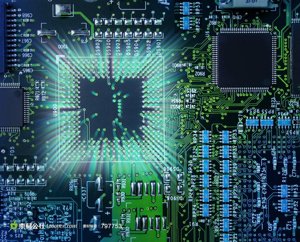
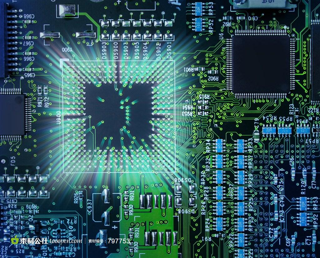
This PCB appearance inspection machine is an important quality inspection equipment for automobile PCB product line It is based on the principle of optical image processing and computer vision recognition technology Its main function is to detect the appearance defects of PCB components encountered in the production process China is a big country in the world, but not a strong country An important link in the PCB production chain - The insecure PCB equipment and instruments is one of the important reasons for this situation In order to promote China's economic development and improve the PCB industry, compared with the automatic appearance inspection machine, the manual PCB appearance inspection machine with simple operation has developed a more compact system and a higher efficiency price ratio Manual PCB board appearance inspection machine automatically transmits PCB board to obtain accurate image through manual board column transfer device and linear array CCD camera scanning PCB board The echo control signal is automatically aligned to the PCB board (OK/NG) It can detect foreign matters, exposed copper, oil supplement, scratches, poor gold plating, wrong characters, uneven green oil, uneven mats, residual copper, lack of printing, development and other appearance defects Because the speed and effect of image acquisition and processing will directly affect the accuracy and effectiveness of image acquisition and processing PCB detection, according to the characteristics of manual visual inspection machine, the image acquisition system was studied in detail, using C # Net framework is used for secondary development of ActiveMil and the development of image acquisition software system is realized with GDI+graphics interface library.
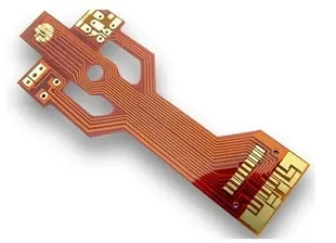
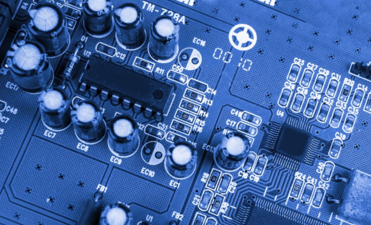
Printed circuit board

1. Overall structure of the project PCB appearance inspection machine system
This PCB online detection system has a complex structure, and its transmission control equipment, power control system and camera must be controlled by a computer to coordinate processing and complete complex detection and sorting tasks On line inspection equipment based on machine vision for structural PCB board. The system is mainly divided into motion control, image acquisition and image processing parts Image acquisition is an important part of the whole system In machine vision, cameras and lenses are equivalent to human eyes and are responsible for capturing images of objects The image acquisition part is an important part of the PCB detection system, which is also the basis of detection processing The PCB inspection system emphasizes the speed and accuracy of inspection. In summary, The image acquisition part needs to provide clear images in a timely and accurate manner
2. The hardware structure of the image acquisition system
2.1 The working principle of the image acquisition system
When the system is powered on, MCU automatically detects whether the PCB level is reset to the starting point This process is mainly completed by two optical fiber sensors and servo motors Two sensors are installed at the starting point of the motor track, namely the reset point and the end point of the track With reset function, stop and motor reverse rotation After power on, the MCU detects that the sensor (reset point or starting point) is invalid, and calls the motor inversion program to return the PCB level to the starting position, and the serial port sends the invalid color image signal to the PC Then, MCU continues to judge whether the key is pressed If you press the key, the motor starts to rotate forward, and the serial port sends a valid color image signal to the PC This process is also the PCB line scanning process to complete image acquisition In this process, the motor goes through three stages: acceleration stage, constant speed stage and deceleration stop stage During the forward rotation of the motor, the MCU counts the pulses fed back by the servo motor encoder through the unique capture and comparison unit (CCU6), but when the count value reaches the effective value of image acquisition, the serial port sends the acquired image to the PC Start the signal. At this time, the linear CCD starts to image the PCB When the motor decelerates forward to the sensor 2 at the end of the track, the motor stops and immediately reverses back to the starting point In this process, the serial port sends an invalid signal to the PC So far, the complete testing process has been completed MCU continues to detect whether to press the button for downward detection Among them, the acquisition and start signals sent by the serial port can effectively avoid false triggering The image signal collected by CCD is sent to the image acquisition card through the Camrelink interface, and then the PC performs further image processing
2.2 Reception and detection of sensors and buttons
Using optocoupler isolation technology can realize optoelectronic isolation between circuits, even if the input signal can pass through without resistance, and prevent the output signal from reverberating to the input terminal, which is conducive to suppressing the interference of spikes and various noises, stable operation, no contact, long service life, and high transmission efficiency In order to detect the echo speed signal of the rotating mirror in real time, this design uses high-speed optocoupler ACPL-072L, the transmission rate can be as high as 25 MBd, and the peripheral circuit is simple The design uses the comparison unit in the captured CC25 port/XC164CS peripheral equipment, and uses the optocoupler transmission signal as the external interrupt signal to trigger XC164, so as to achieve high-speed sensor positioning and button detection
2.3 CCD camera system
The image acquisition system of this manual PCB appearance inspection machine uses the NED rainbow series 3CCD color line scanning camera NUCLi7300. This camera has a wide range of applications, and can perform color difference detection that cannot be achieved by previous black and white cameras The external interface is a high speed serial interface (Camera Link), which can be easily connected to the acquisition card, and can also easily set the gain and offset, and has the function of correcting RGB line delay The number of primitives is 7 300 x 3 lines, the number of points is 10 x 10 mm, the data rate is 60 MHz, and the short scan rate is 7.6 kHz The frame acquisition card in the system is Matrox's SoliosXCL-SU74, which has its own processor to handle two independent basic modes or one intermediate mode camera connection configuration, 66 MHz acquisition rate, 64 MB buffer, and can obtain the array Line scan camera with multiple acquisition modes At present, most of the image inspection systems on the market use area scanning (Arescan) cameras to collect and analyze images However, due to the large size range of PCB boards, the PCB board appearance inspection machine we inspected is - 50 mmx50mm ~ 330mmx250 mm, with high accuracy The resolution and image acquisition speed of the area scanning camera cannot meet these requirements. In summary, the system selects line scanning CCD However, the line scan detection system must use the motion speed to obtain the area shadow. That is, when the PCB is moved to the camera's field of view, the hardware sends a trigger signal to the camera to start the acquisition. Therefore, the acquisition mode of the acquisition card is set to hardware trigger synchronous acquisition and allocate 64 M memory
3. Software system composition
The development language used for the software of the image acquisition system is C # Matrox has a rich package - Image Processing and Pattern Recognition Library (MIL) and MIL's sub library MIL-LITE (Basic Image Processing) MIL is a hardware independent 32-bit image processing library. It optimizes the image processing library by using Intel's MMX multimedia graphics acceleration function, and can process binary files, grayscale or color images. It is independent of the hardware platform For rapid development of Windows applications, the MIL bundle starts the MIL AetiveMIL is a * dynamic control for managing image acquisition Aeti veMIL is fully integrated into Microsoft Visual Basic, a Visual C++and. net rapid application development environment The image acquisition system uses the AETIVEML control library to realize all functions of all MILs. Due to the use of ActiveX controls, it greatly reduces the difficulty of programming, shortens the software development cycle, and improves the stability of the application system
3.1 Image acquisition program based on AclivrMil
The basic idea of the image acquisition program is: 1) Open the communication channel, that is, determine an application object (Application), and create one or more system objects (system) for each application object 2) Initialize hardware resources, that is, allocate data buffer (Data Buffer), data collector (Digitizer) and data display (Display) objects for each system object 3) Start the acquisition process, that is, read the image into the data cache, allocate the cache to the array, and process the image by processing the array After image data is associated with data display, preprocessing can be displayed through display control or form Subsequent results AetiveML allows developers to quickly and easily combine graphical applications with the Windows user interface Application development includes drag and drop and scroll tool placement as well as punctuation and click configuration, greatly reducing the amount of code Exists Net framework 3.0 card hair environment. After the MIL development package is installed and properly configured, components such as application, system, image, image processing and display will be automatically added to the toolbar The developer will drag the required control items to the image acquisition form, the application, corresponding to the single lens manual appearance machine, system a, single form display display. In order to improve the CPU utilization, dual buffer asynchronous acquisition - two ImageBuffers, and one ImageProcess


