The wiring angle of the soft and hard bonding plates is 90 degrees. Is it feasible?
The circuit board manufacturer, circuit board designer and PCBA manufacturer explain to you that the wiring angle of the soft and hard combination board is 90 degrees. Is it feasible?
High frequency and high speed signal transmission lines should not be routed at 90 ° corners, which is strongly required in various PCB Design Guides. Because high frequency and high speed signal transmission lines need to maintain consistent characteristic impedance, and 90 ° corner routing will change the line width at the transmission line corner. The line width at 90 ° corners is about 1.414 times of the normal line width. As the line width changes, it will cause signal reflection. At the same time, The extra parasitic capacitance at the corner will also cause delay effect on signal transmission.
Of course, when the signal propagates along the uniform interconnection line, there will be no distortion of the reflected and transmitted signals. If there is a 90 ° corner on the uniform interconnection line, the width of the pcb transmission line will change at the corner. According to the relevant electromagnetic theory, this will definitely bring about the reflection effect of the signal.

Theoretically, this is true, but the theory is theory after all. Is the impact of 90 ° corner on high-speed signal transmission line decisive?
According to the understanding of the soft and hard combination board factory, the 90 ° corner will have a negative impact on the high-speed signal transmission line, which is certain in theory, but is this impact fatal? Does the 90 ° corner have the same effect on high-speed digital signal and high-frequency microwave signal transmission lines?
For high-speed digital signals, 90 ° corners will have a certain impact on high-speed signal transmission lines. For our high-density high-speed PCBs, the general routing width is 4-5mil, and the electrical capacity of a 90 ° corner is about 10fF. It is estimated that the cumulative delay caused by this capacitance is about 0.25ps. Therefore, the 90 ° corners on the 5mil wire width will not have a great impact on the current high-speed digital signals (100 psc rise time).
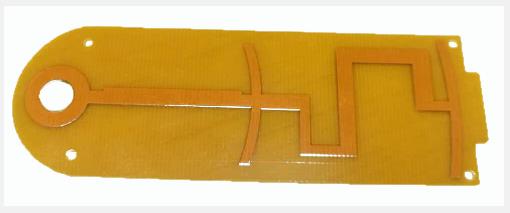
For high-frequency signal transmission lines, in order to avoid signal damage caused by Skin effect, a wider signal transmission line is usually used, such as 50 Ω impedance and 100 mil line width. The line width at the 90 ° corner is about 141 mils, and the signal delay caused by parasitic capacitance is about 25 ps. At this time, the 90 ° corner will cause a very serious impact.
At the same time, the microwave transmission line always hopes to reduce the signal loss as much as possible. The impedance discontinuity at the 90 ° corner and the external parasitic capacitance will cause the phase and amplitude errors of high-frequency signals, the mismatch between input and output, and the possible parasitic coupling, which will lead to the deterioration of circuit performance and affect the transmission characteristics of PCB circuit signals.
With regard to 90 ° signal routing, our point of view is to avoid 90 ° routing as much as possible. Isn't it said that the impact of 90 ° corners on high-speed digital signals can be ignored?
According to the understanding of the soft and hard bonding board factory, of course, the impact of a single 90 ° corner on the signal quality of high-speed digital transmission lines, the deviation from the height of the conductor and the reference plane, the variation deviation of the uniformity of line width and line spacing during the etching process of the conductor itself, the change of the plate dielectric constant on the frequency signal, and even the parasitic parameters of the via are much greater than the problems caused by the 90 ° corner.
However, today's high-speed digital circuit transmission lines can't avoid winding around the same length, overlapping more than ten or twenty corners, and the cumulative impact of the 90 ° corners will cause a signal rise delay that cannot be ignored. High speed signals are always transmitted along the path of impedance, with equal length around 90 ° corners, and the final actual signal transmission path will be slightly shorter than the original.
In addition, the high-speed digital signal transmission rate is becoming higher and higher. The current HDMI2.0 standard, the transmission bandwidth rate has reached 18Gbps. The 90 ° corner routing will no longer meet the requirements, and it is now the 21st century. Even those who use the EDA software now support the 45 ° routing very well.
At the same time, the 90 ° corner routing does not conform to people's aesthetic standards in terms of engineering aesthetics. Therefore, for the current layout, whether you are using high-frequency/high-speed signal lines or not, we should try to avoid using 90 ° corners for routing, unless there are special requirements.
According to the understanding of the soft and hard bonding plate factory, for the high current wiring, sometimes we will replace the wiring with copper sheet. At the corner of copper laying, we also need to replace the 90 ° corner with two 45 ° corners. This is not only beautiful, but also does not have EMI potential. The circuit board manufacturer, circuit board designer and PCBA manufacturer explain to you that the wiring angle of the soft and hard combination board is 90 degrees. Is it feasible?


