This is also a common phenomenon in the process of debugging, frequency reduction is mainly caused by two aspects. The input voltage and load voltage ratio is small, the system interference is large. For the former, be careful not to set the load voltage too high, although the load voltage is high, the efficiency will be high. For the latter, try the following:
1. Set the small current lower;
2. Clean wiring, especially the critical path of sense;
3. Select a small inductance or the inductance of a closed magnetic circuit;
4. Add RC low-pass filtering. The effect is a little bad. The consistency of C is not good and the deviation is a little large, but it should be enough for lighting.
There is no upside to downscaling anyway, only downside, so be sure to fix it.
Choice of inductor or transformer
With the same drive circuit, the inductance produced by a has no problem, and the inductance current produced by b becomes smaller. In this case, look at the inductive current waveform. Some do not notice this phenomenon, directly adjust the sense resistance or working frequency to reach the required current, which may seriously affect the service life of LED.
Therefore, before the design, reasonable calculation is perfect, if the theoretical calculation parameters and debugging parameters are a little far away, to consider whether the frequency reduction and transformer saturation. When the transformer is saturated, L will become smaller, resulting in a sharp rise in the peak current increment caused by transmission delay, so the peak current of LED will also increase. If the average current stays the same, you can only watch the light fade.
LED current size
We all know that if the LED ripple is too large, the LED life will be affected, how much impact, have not seen which said. I have asked the LED factory about this data before, and they said it is acceptable within 30%, but it has not been verified later. I suggest keeping it as small as possible. If the heat dissipation is not solved well, the LED must be derated. I also hope to have a specific index, otherwise it will affect the promotion of LED.

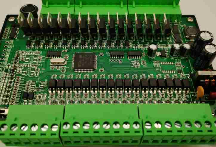
1. Opening principle: cut aniseed into small materials according to the size required by MI. 2. Paste dry film or printing oil, exposure etching back film inner layer corrosion detection is a process of graphic transfer, through the use of film negative, ink/dry film and other media under ultraviolet light, the line graphic required by the customer is made on the inner layer substrate, and then the unnecessary copper foil etching away, finally made into the inner layer of conductive lines. Pre-treatment: grinding plate inner dry film inner etching inner test + coarse copper plate surface, in order to increase the binding force of the board and film + clean the board, get rid of the dry film and copper foil covering ink and copper foil covering 3. 4. Drilling process: The role of drilling: to produce a conductive channel 5 on the circuit board that allows the later process to complete the connection between the upper/lower or intermediate circuit layers. Wet process: copper sedimentation - outer dry film - graphic plating or plate plating - outer - etching plate - outer - etching copper detection action: deposit a layer of conductive copper layer on the hole wall of the circuit board insulation, conduction and the connection of the inner line. Outer dry film: stick dry film exposure image plating or plate plating: Function: increase the copper thickness of the circuit board hole \ wire \ face, so as to meet customer requirements. Outer etching: film retreat: The use of strong alkali can make the dry film dissolution or peeling properties of the unwanted dry film from the surface peel or dissolve corrosion plate: the use of bivalence copper ammonium and ion oxidation to the unwanted copper from the plate corrosion tin: The nitric acid in the tin removal water is used to react with tin to remove the tin layer from the board to the outer layer inspection :AOI&VRS takes the PCB image by CCD scanning, compares it with CAM standard graphics by computer and processes the logic of the design specification, marks the bad spots on the circuit board and sends the coordinates of the bad spots to the VRS, and finally confirms the bad spots 6. Wet film process: the main process stations include: printing a layer of photosensitive ink on the molded outer wire board surface and curing it to protect the outer layer and insulation of the circuit board; pre-treatment grinding board, ink printing, oven exposure and image printing, character printing 7. Surface treatment process: mainly according to the requirements of customers, the circuit board copper surface for a layer processing. The main processing processes are: spray tin: spray a layer of weldable tin surface on the copper surface using hot air welding process. Tin sinking: The use of chemical principles through chemical treatment to deposit tin on the surface of the board. Silking: The depositing of silver on a surface by chemical processes. Gold deposition: The use of chemical principles to deposit gold on a surface. Gold plating: Using the principle of electroplating, through the current and voltage control of gold plating on the surface. Anti-oxidation: Using chemical principles to apply an anti-oxidation chemical to the surface 8. Molding process: Mainly according to the customer's requirements, a formed circuit board is processed into the size and shape required by the customer. Open and short circuit test inspection: mainly to check the open circuit and short circuit inspection of the line, as well as the use of visual inspection board quality. Packaging and shipment: the qualified board will be packaged and finally shipped to the customer.


